This page is a deep dive into the physical design of roons.
If you’d like an overview of our workshop and manufacturing instead, click here.
vertical movement
How do we make bars move up and down?
This sounds like the easiest problem in the world, but it took us a long time to solve, and we’re still refining it.
Our early prototypes used a cam system linked by gears.
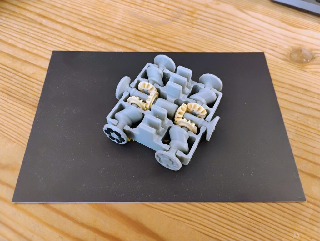
This system had a few problems:
- It takes up a lot of vertical space — we want the drives as flat as possible.
- With such small gears, there’s a lost of backlash or “play”. They’re always a few degrees out of sync with each other, so the bars end up tilting.
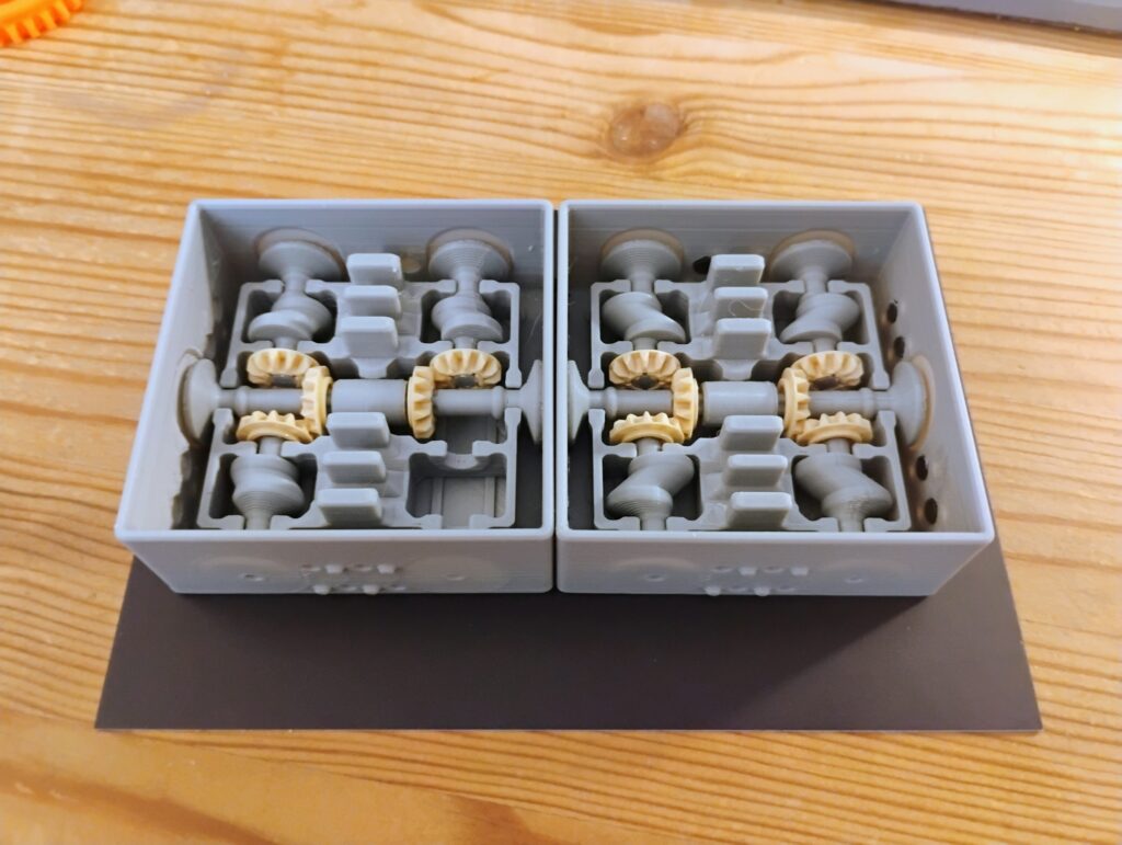
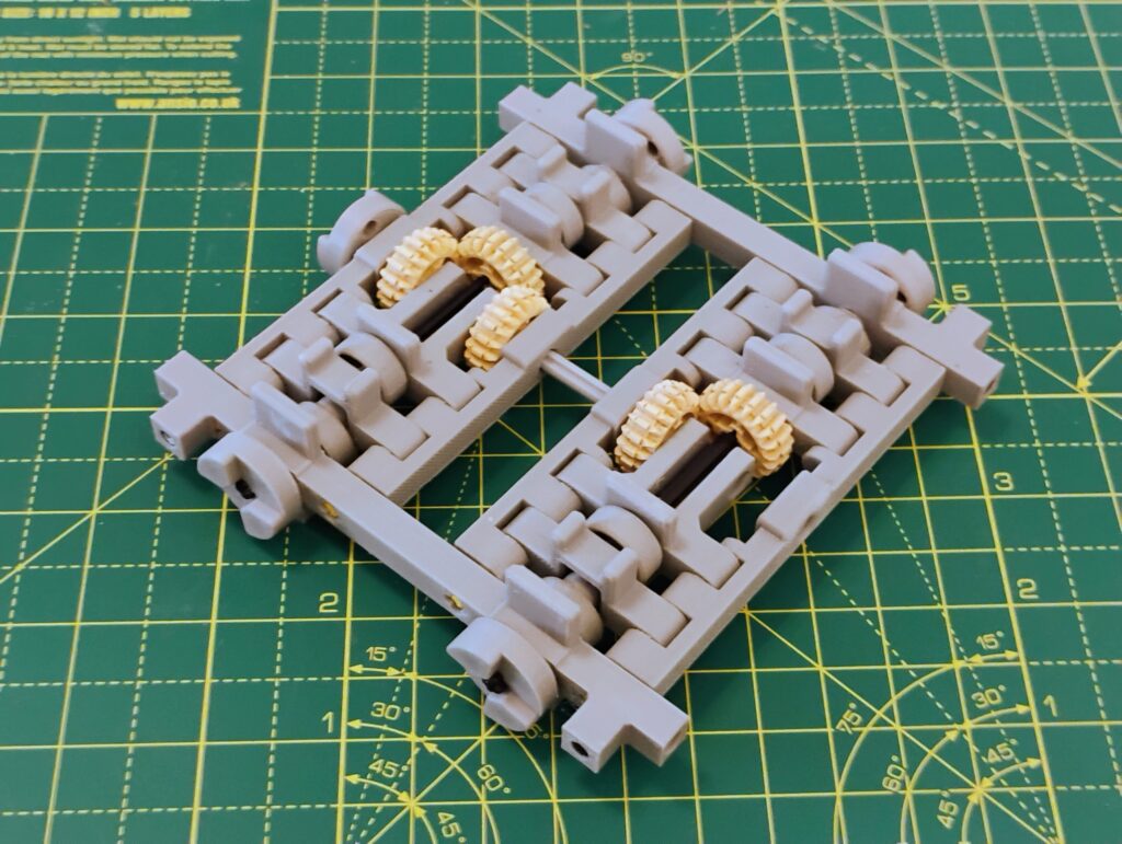
To solve this, we switched to barrel cams:
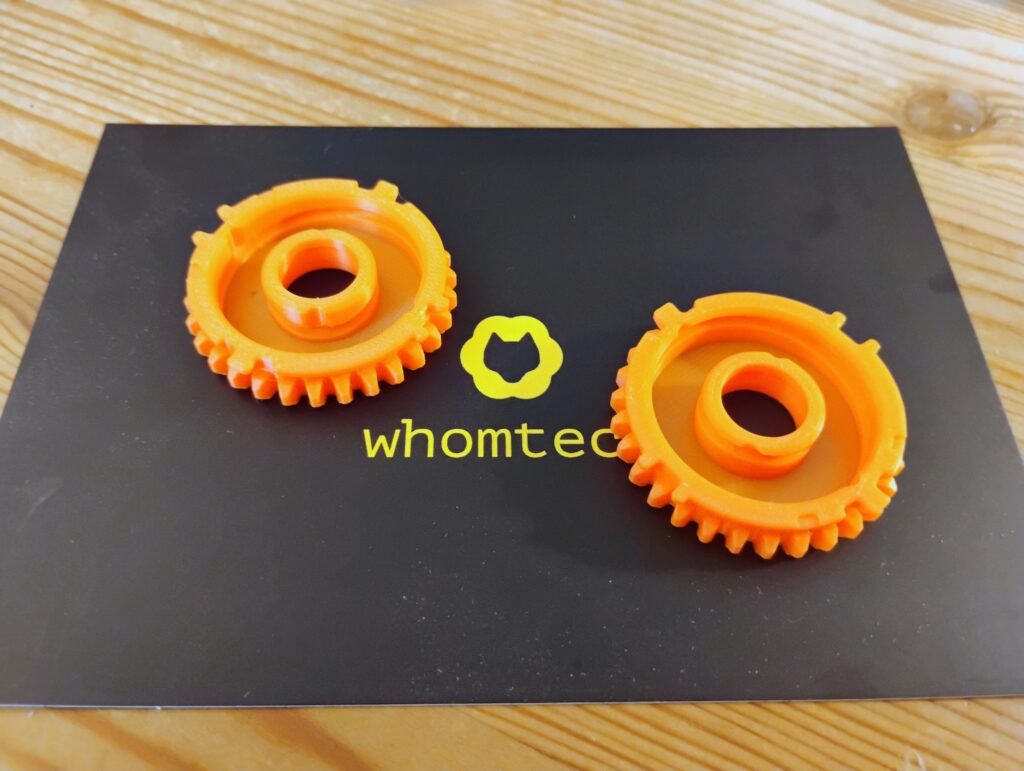
These larger gears are much more stable and have less play in them….
But they give us a new issue: friction. Barrel cams are inherently quite high friction, as the follower (the nub that attaches to the cam) has to slide along the groove. Followers are often designed to rotate to reduce friction, but these cams are too small to support a rotating follower. Instead, we have a few techniques for minimising the problem:
- Optimise the shape of the groove and follower
- Sanding to smooth them down
- Applying a PTFE spray (teflon) as a dry lubricant
This is an active area of development — our prototypes are currently limited by what tech we have access to. With Kickstarter funding we’ll be able to get these spinning even more smoothly.
power grid
Early on, we decided that we wanted roons drives to be tileable, so users could flexibly adjust the size of their workspace. To do this, we needed a system to transfer power automatically across the grid.
We prototyped a few approaches. Initially, when we were using horizontal cams, we used magnetic couplers to invisibly transfer power.
It looked really cool, but wasn’t quite reliable enough. So then we exposed the couplers to increase the power they could deliver without slipping.
But ultimately, as you’ve seen, we switched across to vertically mounted barrel cams. This actually made the power transfer much easier. We don’t need any special adapters or couplers — the interface between each drive is identical to how the gears bind inside the drive! In other words, when we put multiple drives together, the underlying gear grid is entirely homogeneous; it has no concept of “drive boundaries”, it’s just a continuous grid.
gear design
Each gear has 30 teeth. This gives us decent tooth size, so they’re durable, easy to manufacture, and have good power transfer.
But we specifically chose 30 because it’s half-odd — i.e. it divides by 2, but not by 4.
Let’s consider the north face of a drive. It exposes 2 gears, A and B, that need to mesh with the south face of another drive. Because A and B are meshed together, they’re offset from each other by half a tooth (otherwise their teeth would intersect). So when A has a tooth pointing directly north, B has a hole pointing north.
But each drive has 90 degree rotation symmetry. And each gear sits on a corner, so it’s a member of 2 faces. This means that B also sits on the east face of the drive. If we rotate the drive 90 degrees anticlockwise, B is now where A was; and its previously eastern point is now its northern point. But A’s northern point was a tooth, and to maintain symmetry, that’s what B needs.
(I promise I’ll upload diagrams soon!)
Therefore B needs a hole on its northern point, but a tooth on its eastern point. The same is true for its southern/western points. This is only possible with a half-odd number of teeth. If the number of teeth were divisible by 4, then these sites would all have to look the same.
And that’s why we use 30 teeth.
grid design
Each cell is 1/2.5th of an inch across (approx 1/20,000th of a furlong). We call this new unit a centimetre. Each board is comprised of 8×8 cells, making it 8 “centimetres” across.
prototyping grid
When we were prototyping, we initially used cells 0.8 cm across. Why? Because that’s what Lego uses. This let us rapidly prototype big designs by using mostly Lego, and only 3D printing some small bespoke parts.
… however, 8mm is just too finnicky:
- 8mm plastic ball bearings are half the weight of 10mm ones — which are already very light — so they have a tendency to fly off the board.
- We kept running up against the tolerance limits of our 3D printing setup
At a certain point we made the decision to scale everything up 25% to the 1 cm mark.
gridfinity
We use gridfinity, a modular grid system, to organise our workshop. It’s simple and good, and has a ton of community support.
So we thought, hey, wouldn’t it be cool if roons were compatible with gridfinity?
But… gridfinity uses a 42mm grid system, which would’ve forced us to move from 80mm boards to 84mm (i.e. covering 2 gridfinity cells). So each roons cell would be 10.5mm which is just slightly too annoying when I’m designing all these parts.
We’re still considering this, so if you’re a pro- or anti-gridfinity advocate, make your case! We may need to adopt some kind of grid base for larger devices (as the magnets stop being strong enough at high torque), so making a smart decision here will pay off later.
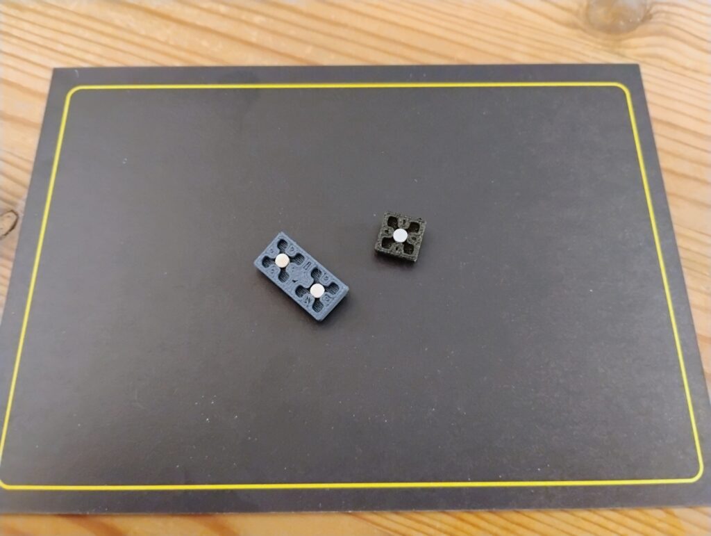
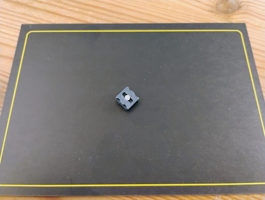
stud system
We needed a a way to connect roons to the disk. Initially we used Lego-style studs. There are a few problems here:
- It’s difficult to reliably 3D print studs with a firm “clicking” motion
- It’s actually quite fiddly to add/remove roons to a disk when you have to click them into place
- Because studs are round, 1-cell roons like the path
 are free to rotate — this is bad!
We ended up using magnets. This works great for binding roons to the disk, but it doesn’t confine their horizontal position enough.
Therefore, we added in a 2×2 grid of miniature studs on each cell. This locks each roons’s position and rotation, while the magnet handles the vertical binding.
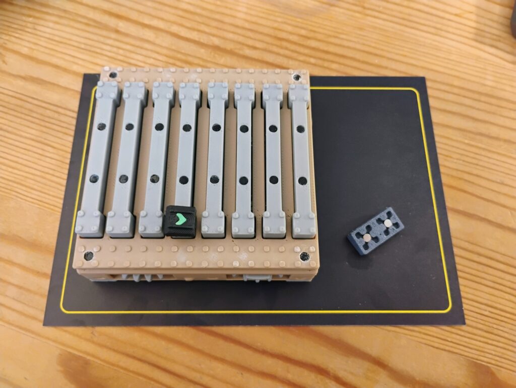
What’s cool about this: it means we can actually position roons at a 1/2 cell offset, by straddling half of the 2×2 grids of two adjacent cells. This is a huge convenience, because many roons (e.g. the switch  ) output their results on a 1/2-cell level.
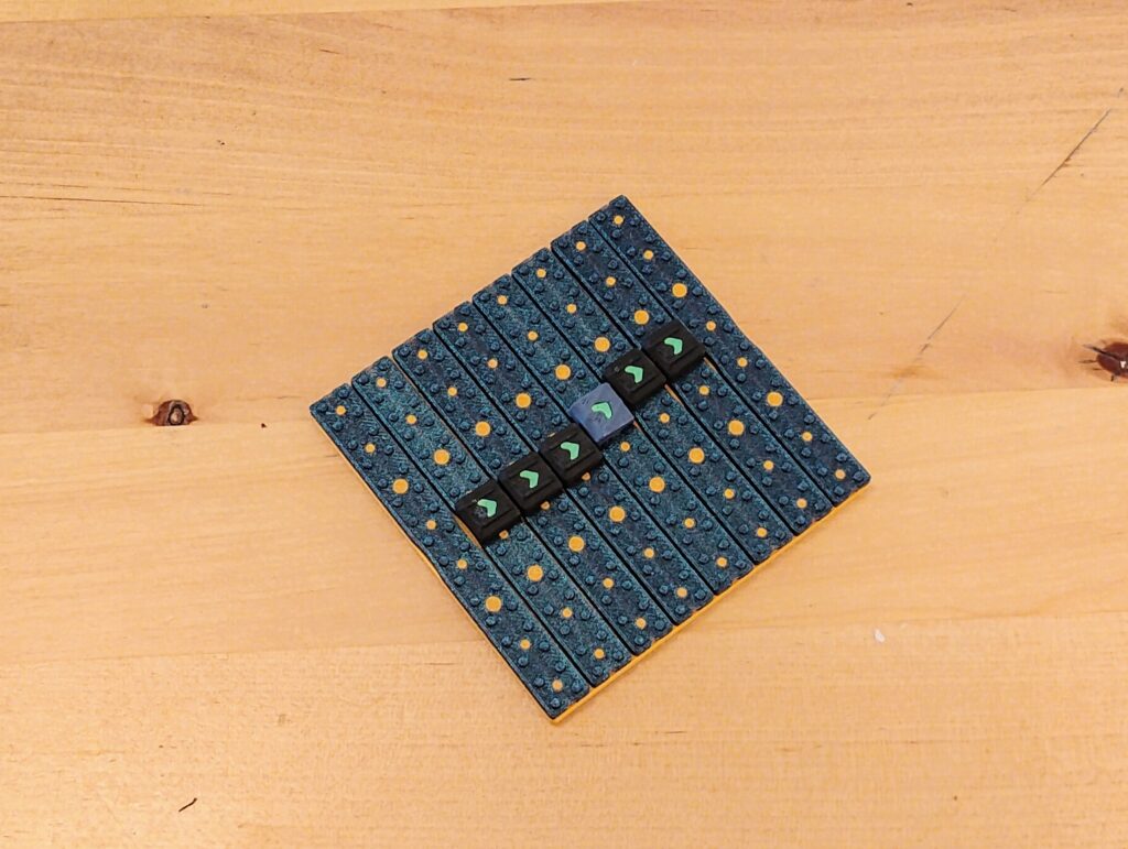
One fun detail: there’s exactly one roon, the shimmy  , that has to sit at a 1/4 cell offset, because it connects up roons that are 1/2 a cell apart. We had to design a special base for this one.
bars
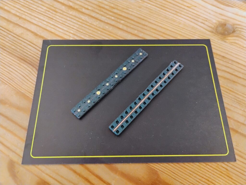
Creating magnetically receptive bars was surprisingly challenging. Initially we just used magnets, but that would require 120 magnets per disk — not only tedious, but the magnets are powerful enough to interfere with the adjacent bars.
So next we used “fridge material”, i.e. sheets of hobbyist black rubber steel. We wasted far too much time trying to shape this — we cut it with a craft knife, guillotined it, punched buttons out of it with a hole punch. But always the cutting would deform it too much to be usable. Also, integrating the shape into a bar, while locking the roons in place, and also maintaining magnetic strength, was basically impossible.
So then we looked at using magnetic PLA, which would likely have broken our printers and not worked very well.
So then we looked at using magnetic resins and paint, which wouldn’t be feasible with the specific shapes we needed.
So then we looked at embedding small metal sheets, but couldn’t find a way to manufacture anything at the tolerances and scale we needed.
So then we looked at embedding a small wire or rod, but couldn’t find ones that were magnetic and available in the form factor we needed.
So then we sort of just bashed our heads against the wall for a while, and nearly gave up.
… then we revisited the rod idea, and stumbled across Copper-Coated Mild Steel (CCMS) brazing rods.
CCMS brazing rods are used for welding and restoring my sanity. You can get them 1.6mm thick, which is just thin enough to cut manually with some bolt cutters. They’ve give you good magnetic binding, they’re rust resistant, and they’re dirt cheap.
Our 3D printing setup needs at least 0.4 mm of PLA to get a reasonably opaque surface. Embedding a brazing rod directly underneath 0.4mm of PLA gives us just strong enough magnetic reception at the surface, allowing us to hide the rod away.
more info
If you’d like us to add more info on any particular area, get in touch at support@whomtech.tech.